Wiring limit switch diagram box pneumatic actuator its sk Valve zone 24vac relay detecting cycle end 1311 circuits thermostat spdt input Switch limit installation wiring lift boat remote gem adjustment tec rotary screwdriver head phillips slotted required tools small
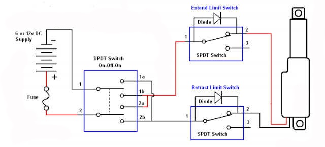
Limit switch to stop DC motor
Limit switch valve components switches actuators introduction mounting ball Limit switch wiring linear switches diodes slider diode Limit switch box iecex wiring diagram actuator pneumatic close open
Wiring & installation
Motorized ball valveValve need Modular nachi drain valve pressure switch non type wiring exampleLimit switch diagram wiring valve motor cr stop dc way.
Float relay controlling motorized appliance wiringValve switch switching diagram valves Limit switch wiring diagram / limit switch working principle yourWiring diagram limit switch.

Honeywell thermostat diagramweb heat propane jumper
Switches normally instrumentation instrumentationtools referred incorporates bothSwitch limit wiring diagram westlock valve Limit switch wiring diagram motorLimitorque actuator l120.
Switching valvesNon drain type pressure switch modular valve Industrial valve, pneumatic components and valve automation in barodaSwitches valves.

Switch limit wiring diagram motor reversing ac wire switches control direction farmall fan relay electrical open honeywell power starting cycle
Limit switch to stop dc motorLinear actuator limit switch wiring Controlling appliance motorized circuit stackActuator switches actuonix.
Iecex rated limit switch boxHow to use an external limit switch kit with a linear actuator Introduction to limit switches for actuators – plast-o-matic valves, inc.How do you control 1 solenoid valve from 2 sources?.

Switches and valves
Valve ball digitaltech motorizedHad to drop valve body to replace now i can't get the valve Valve solenoid switch level liquid circuit water stackWestlock limit switch wiring diagram.
Electric valve actuator wiring diagramLimit switch wiring valve diagram How the honeywell fan and limit switch works.Thermostat wiring diagram honeywell limit switch fan heat diagrams pump hvac room wire systems t87 control thermostats high programmable library.

Wiring diagram limit switch
Switches honeywellLimit control Basics of limit switches instrumentation toolsDetecting end-of-cycle for 24vac zone valve.
Wiring diagram pdf drain valve switch formatWiring diagram occupancy sensor switch limit ceiling aux sponsored links .

LIMIT CONTROL - JapaneseClass.jp

relay - limit switches to control motor direction - Electrical
Introduction to Limit Switches for Actuators – Plast-O-Matic Valves, Inc.

Non Drain Type Pressure Switch Modular Valve - Valves - Hydraulics

Basics of Limit switches Instrumentation Tools

Wiring Diagram Limit Switch

Wiring